
Formula SAE Drill Jig Project

image (10)

Throughout my college career, Formula SAE at Iowa State has enveloped my attention. I was first on the powertrain team during my freshman year and switched to suspension my sophomore year due to the team’s imminent switch to EV.

20250515 221914000 ios

CR-28 at Formula SAE IC Michigan 2025
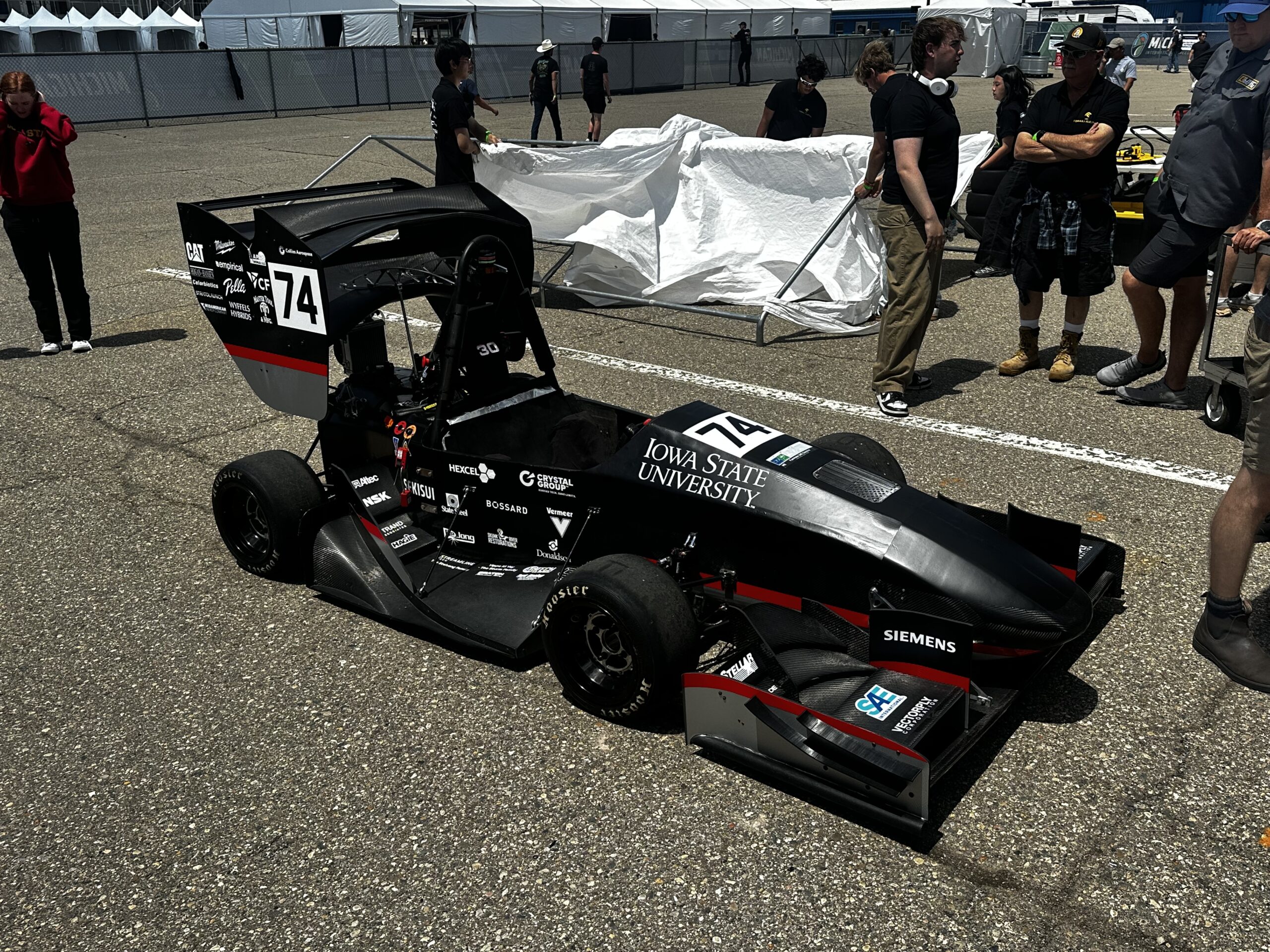
CR-30, Cyclone Racing’s 2025-2026 car, made several breakthrough firsts for the club. As mentioned earlier, it was the team’s first successful EV powertrain car, after 29 years of internal combustion (IC) competition. Along with that, it was the first full carbon fiber monocoque chassis, after several years of running a half-monocoque configuration.

20260620 180600275 ios

CR-30 at Formula SAE EV Michigan 2026
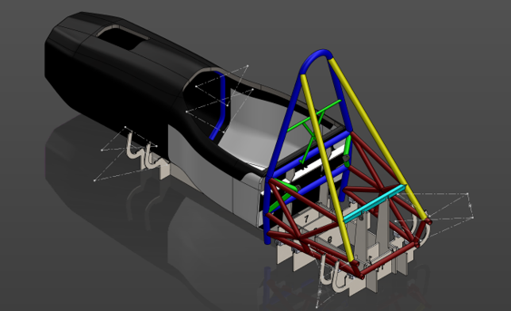
With these new improvements came new challenges. In manufacturing our previous chassis, a sheet metal welded jig was used to weld the steel tube-rear portion, as well as provide reference points for the fore suspension mounting points throughout the whole chassis assembly, as seen below.

picture1

CR-28's chassis welding and assembly fixture
However, as mentioned above, this style of jig could not be used again for our new full monocoque chassis. Tubes did not exist as certified hard points, and the monocoque needed to be consistently referenced for accurate suspension geometry. So, a task to develop a drill-point jig for all suspension components and several final drive components fell on me, with the following parameters:

  • Accuracy to within 1/8 in. between driver and passenger side
  • Support weight of chassis
  • Ease of drilling

For my design, I followed the basic principles that CR-28’s jig followed. Although other materials, such as acrylic, were considered, a sheet metal sponsorship we had made it an easy financial choice. 1/4 in. steel was chosen to be generous and prevent deflection seen as the chassis rested on the main rails. For the hole indicators, FDM 3D printing was the chosen manufacturing process, as it was easy to replicate and make quick changes in our tight timeline of several weeks.

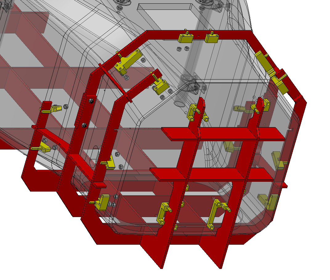
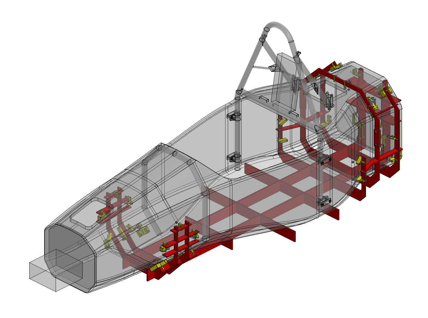
For modeling the jig, I used SolidWorks to seamlessly work around the chassis. As previously said, the prior jigs had worked well, so I iterated and followed a similar 3D-puzzle type of build. Ribs were placed close to every modeled hole, as well as additional weight distribution crosses.

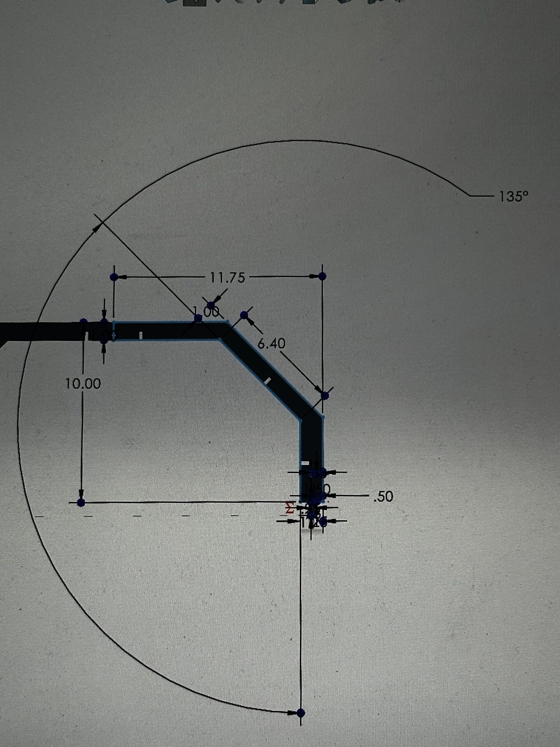
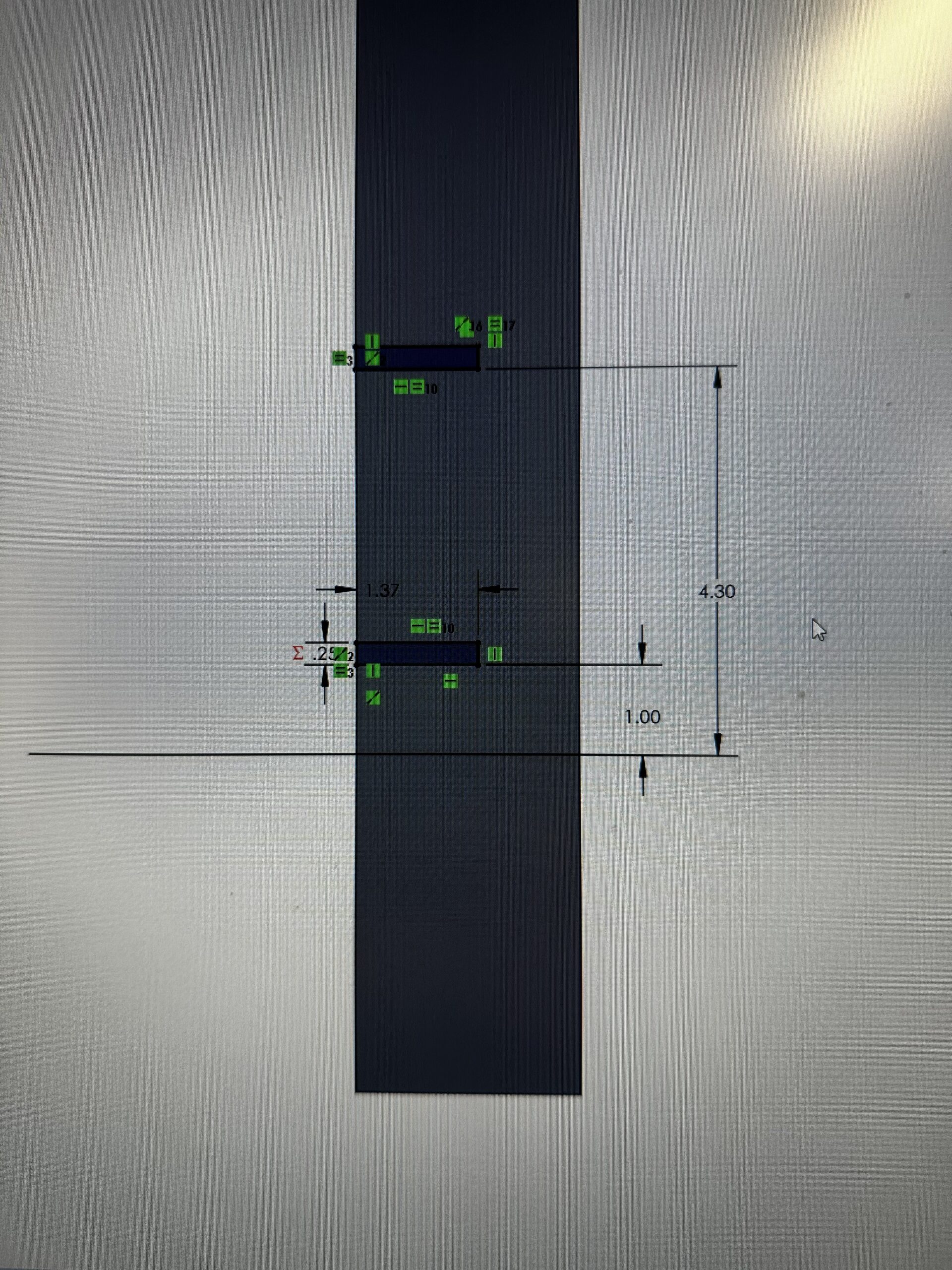
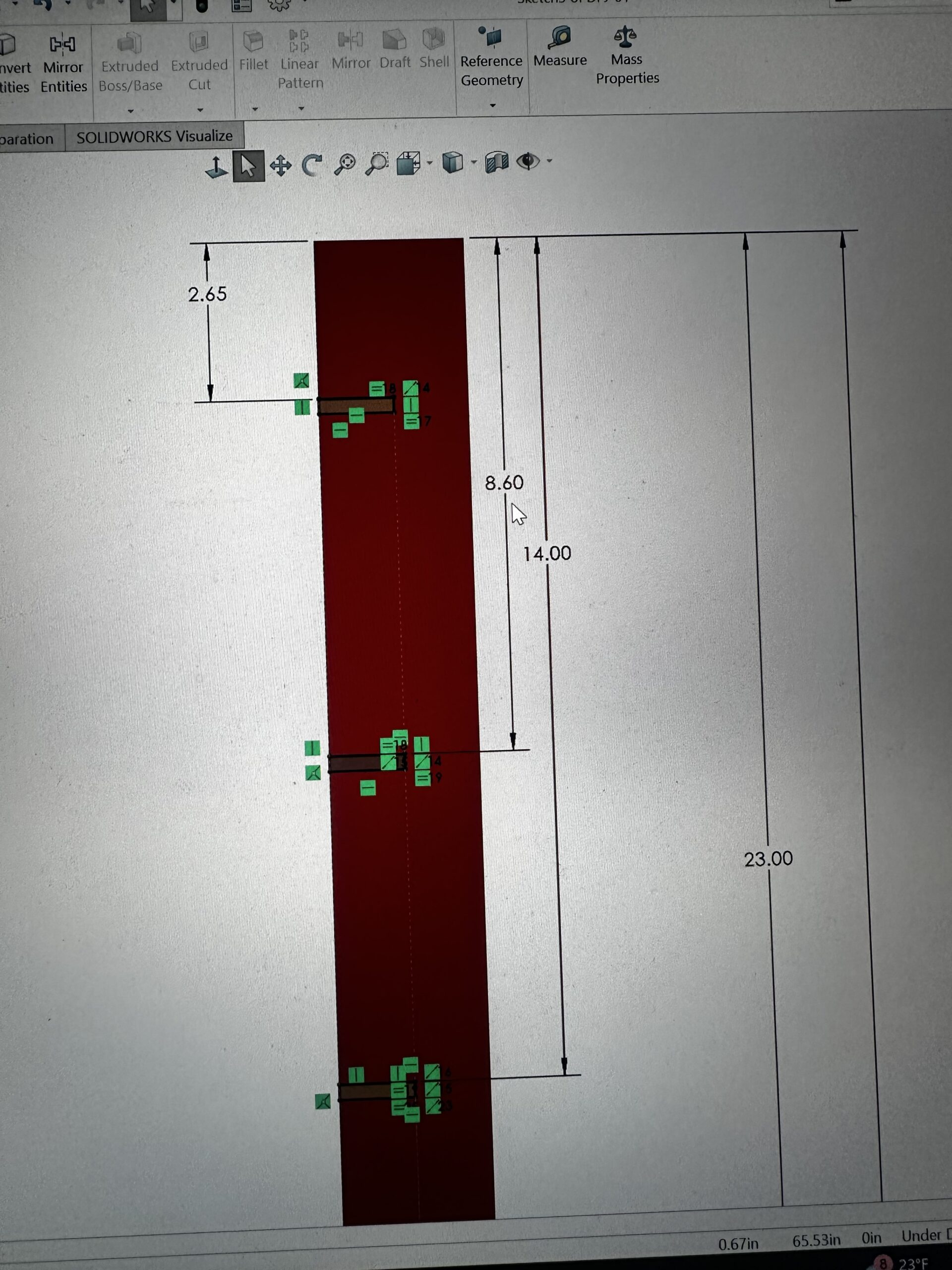
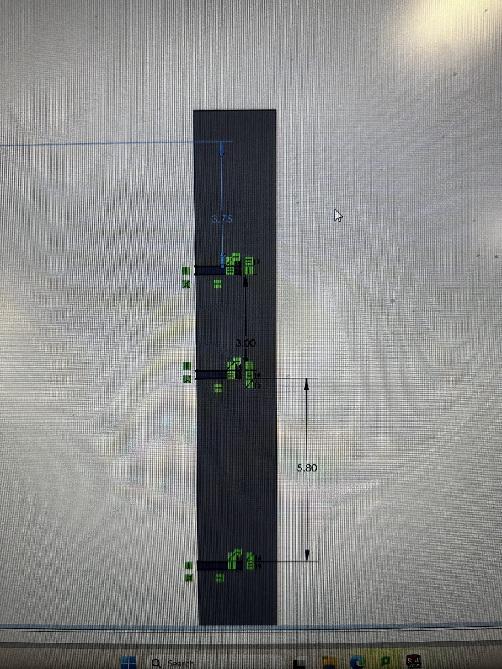
Various sheetmetal modeling pictures taken during design stage

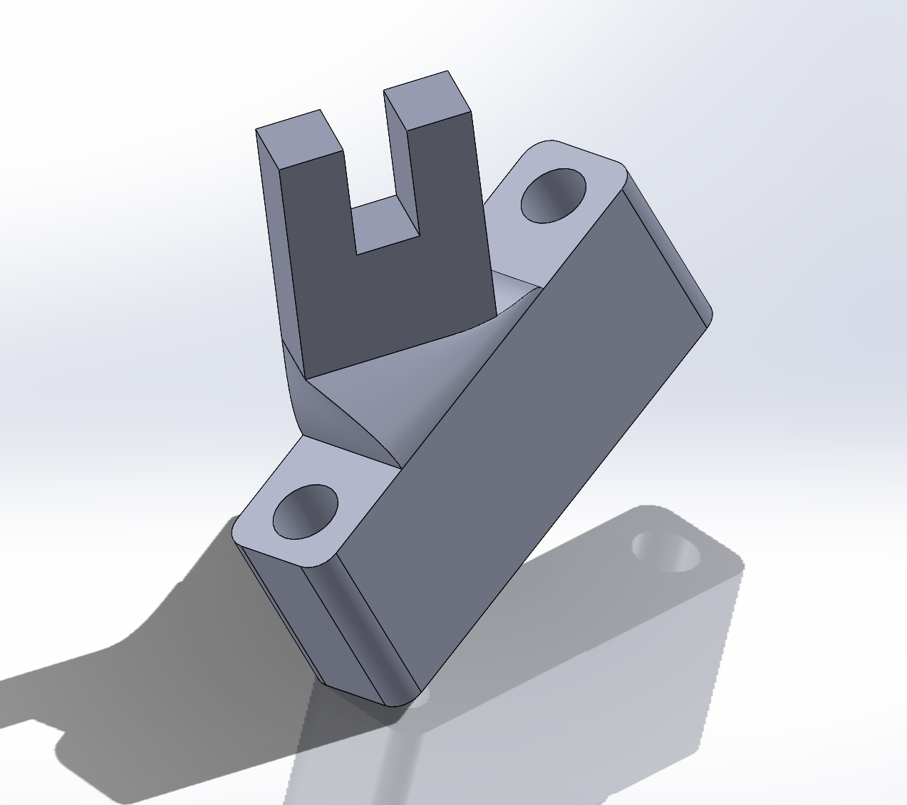
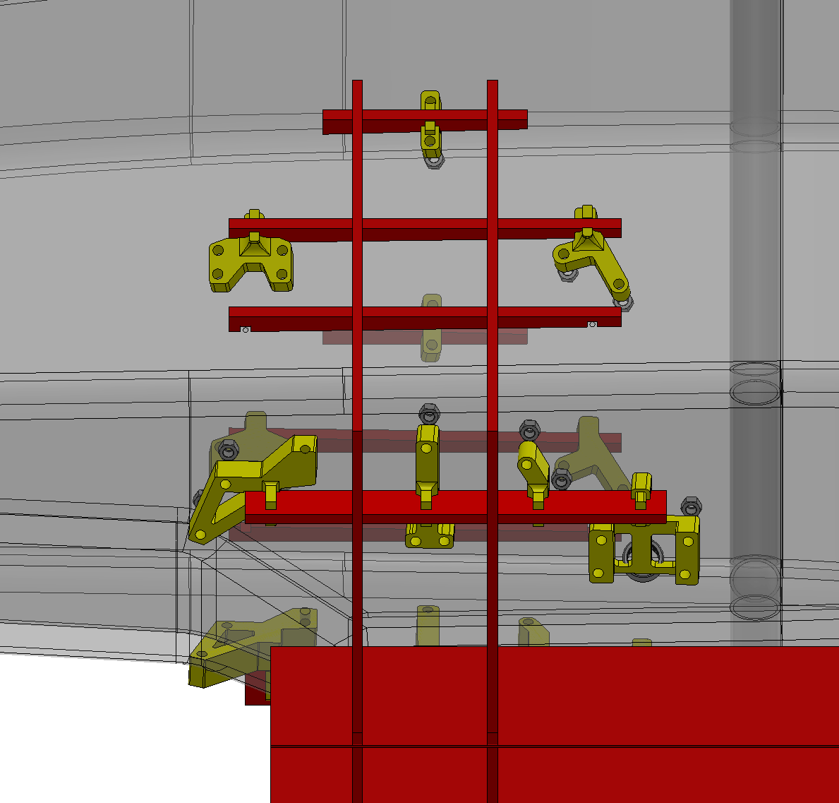
An issue I ran into early was planning how to get the rear suspension holes, which were on top of the chassis, drilled. Given that the chassis had to be inserted, I designed a split hoop to go around the rear of the chassis which would be fastened once the chassis was seated. The 3D prints were relatively simple, as I made each 1 in. tall to prevent the drill from wobbling, created robust slot fingers to lock onto the sheet metal jig, and the holes were simply lined up with the holes on the chassis model.

Various images of 3D Prints in SolidWorks, as well as hoop design

screenshot 2026 07 18 044625

Finalized SolidWorks CAD model of jig
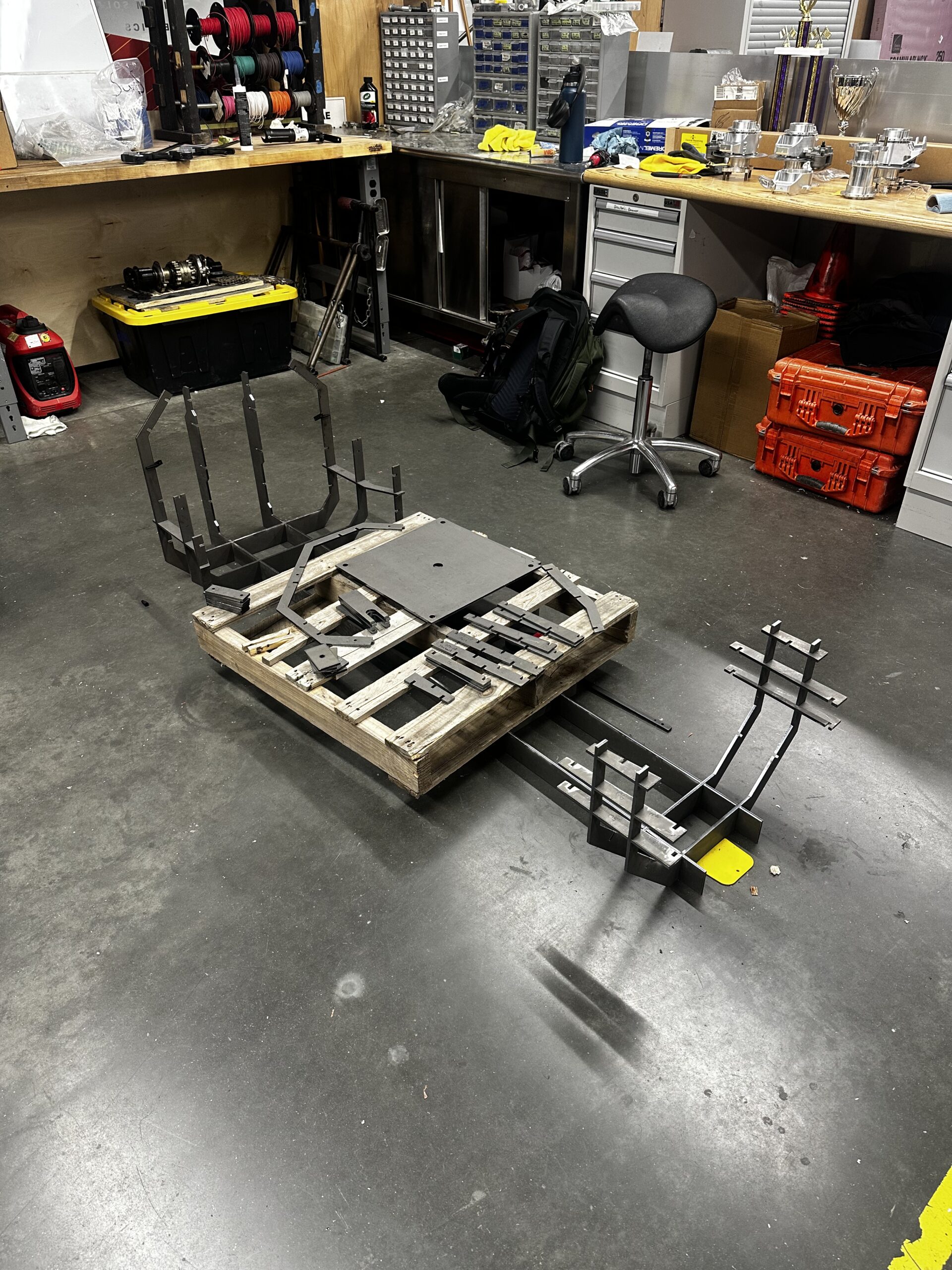
Fast forward several months, and the material was in.

20260129 021247645 ios

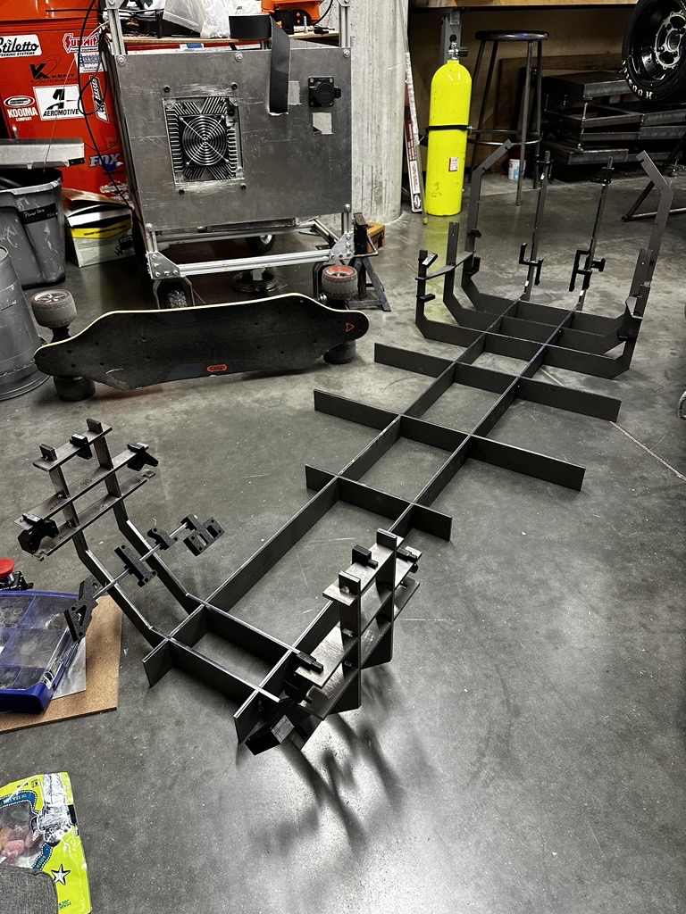
Sheet metal portion of jig slotted together upon supplies arrival
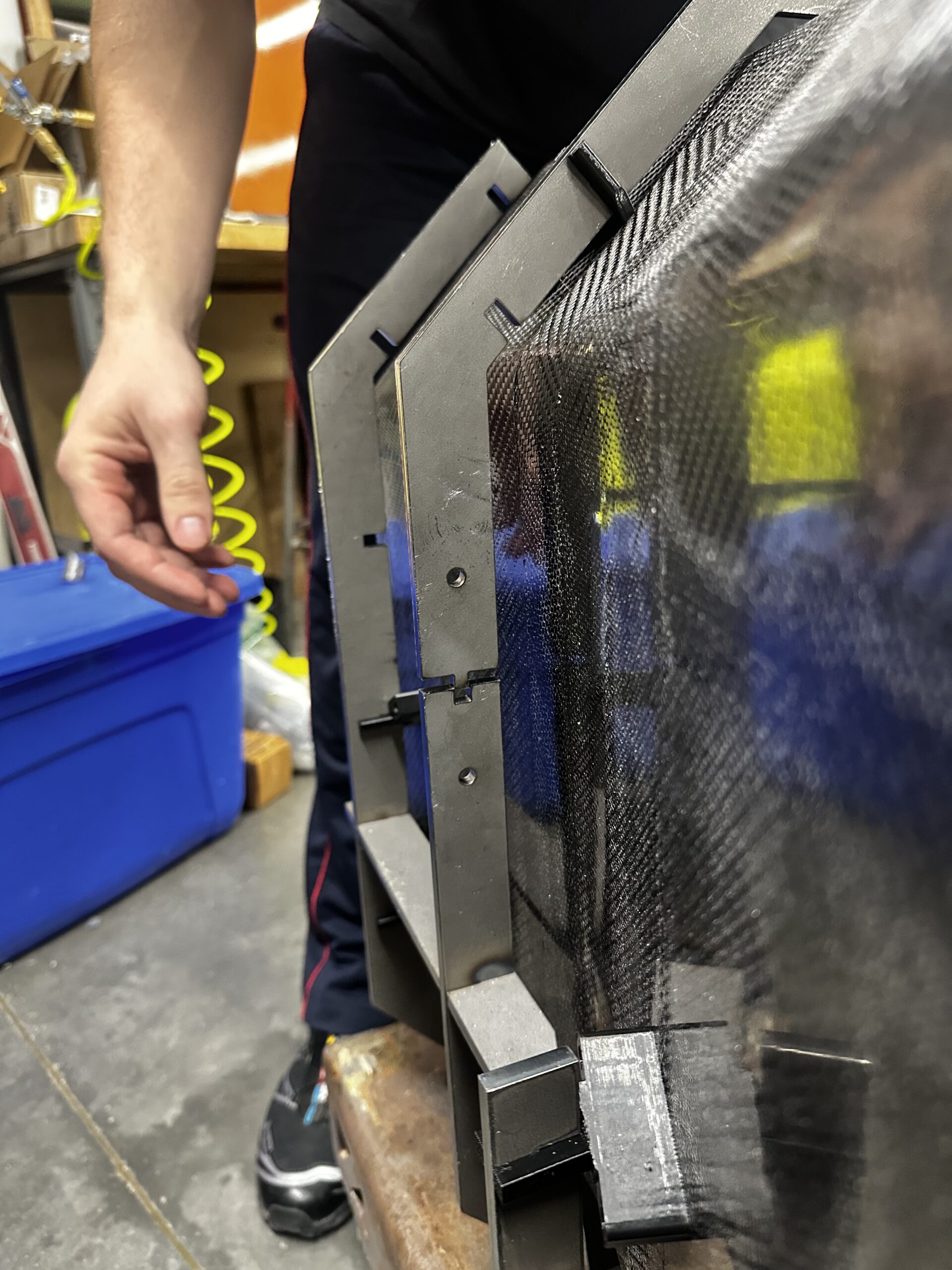
The plan was to tack weld the jig together, slot the 3D printed portions in, slide the chassis in, and drill away. After welding, assembly, and getting the chassis in, a problem was discovered: the top and bottom of the rear jig hoop had roughly a 1/4 in. gap between both pieces.

20260208 215315910 ios

Gap seen by both sides of jig hoop; roughly 1/4 in. in size
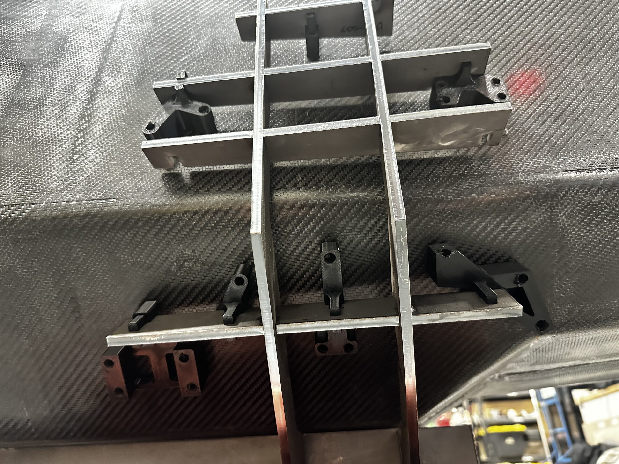
It was determined that this was caused by a high point on the chassis and was fixed by working with the Spring and Damper Engineer to adjust for the difference seen by the gap. After drilling the holes in the rear, a second issue was discovered. When welding, robustly fixturing the jig was overlooked, and the issue was only discovered after the chassis drilled into on both sides and over a ¼ in. difference was seen driver to passenger side. Thankfully, this chassis ended up being replaced due to other reasons, but the jig had the welds ground down, and it was re-welded using much more secure fixtures, frequent square checks, and slight offsets to account for relaxing. A maximum difference of 1/32 in. was seen from left to right at the end.

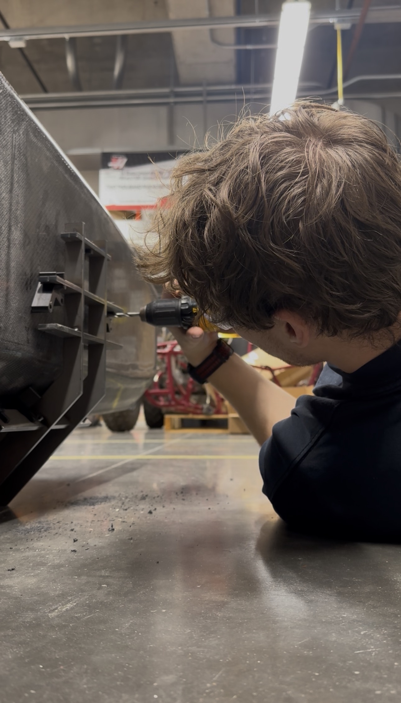
When drilling, a third, smaller issue arose. The 3D printed material that was chosen was PETG for its high thermal resistance against the drill bit, but the bit was still able to wallow through the side of the hole and wobble if the drill was not held straight. This problem was solved by holding the drill perpendicular to the surfaces, with several spotters checking. If I were to do this again, however, I would include metal sleeves in the drill hole portions to allow for the alignment holes to truly do all the alignment.

img 1457

Several wallowed-out 3D prints after drilling
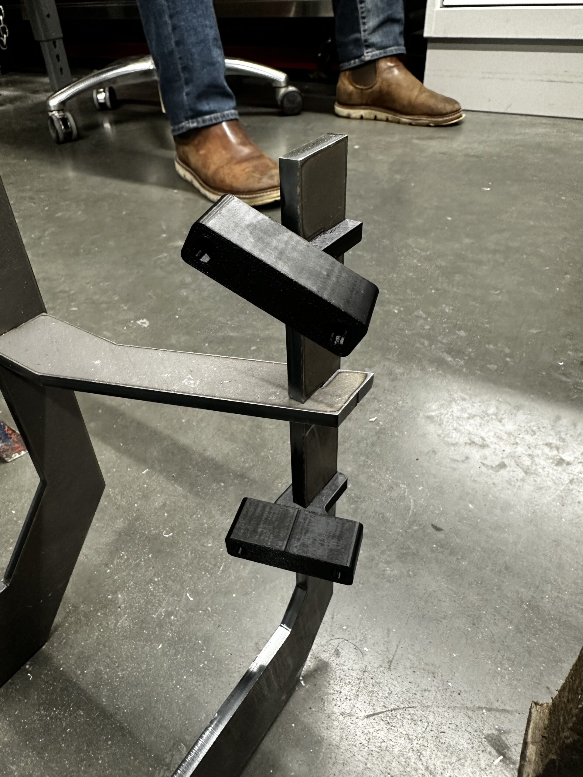
Ultimately, the project was a success. The anti-roll bar spun with almost zero friction, and the maximum difference seen from driver to passenger side was 1/32 in. on the used chassis. I learned how to work until tight deadlines, how to recover from problems, and how to avoid those problems in the first place.

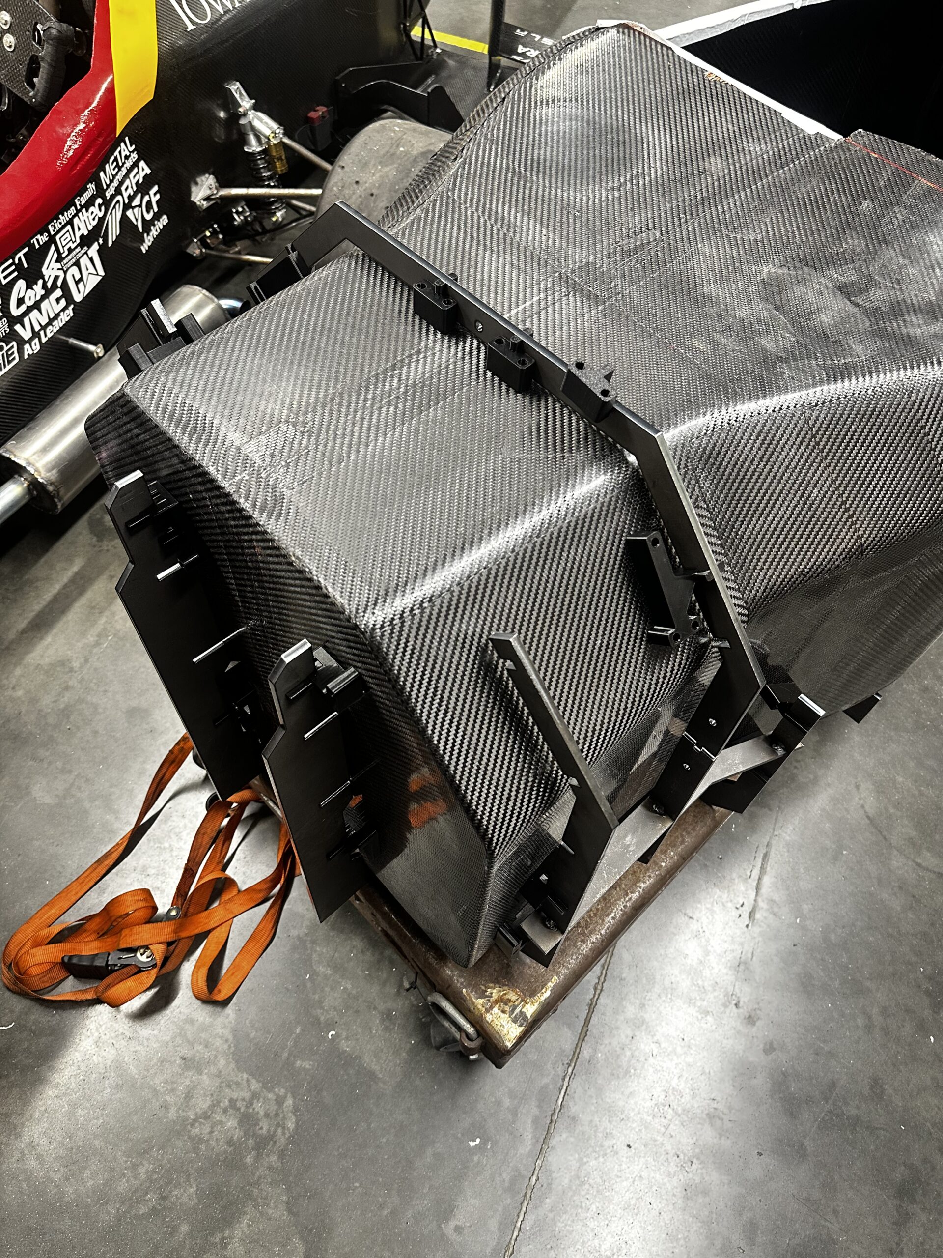
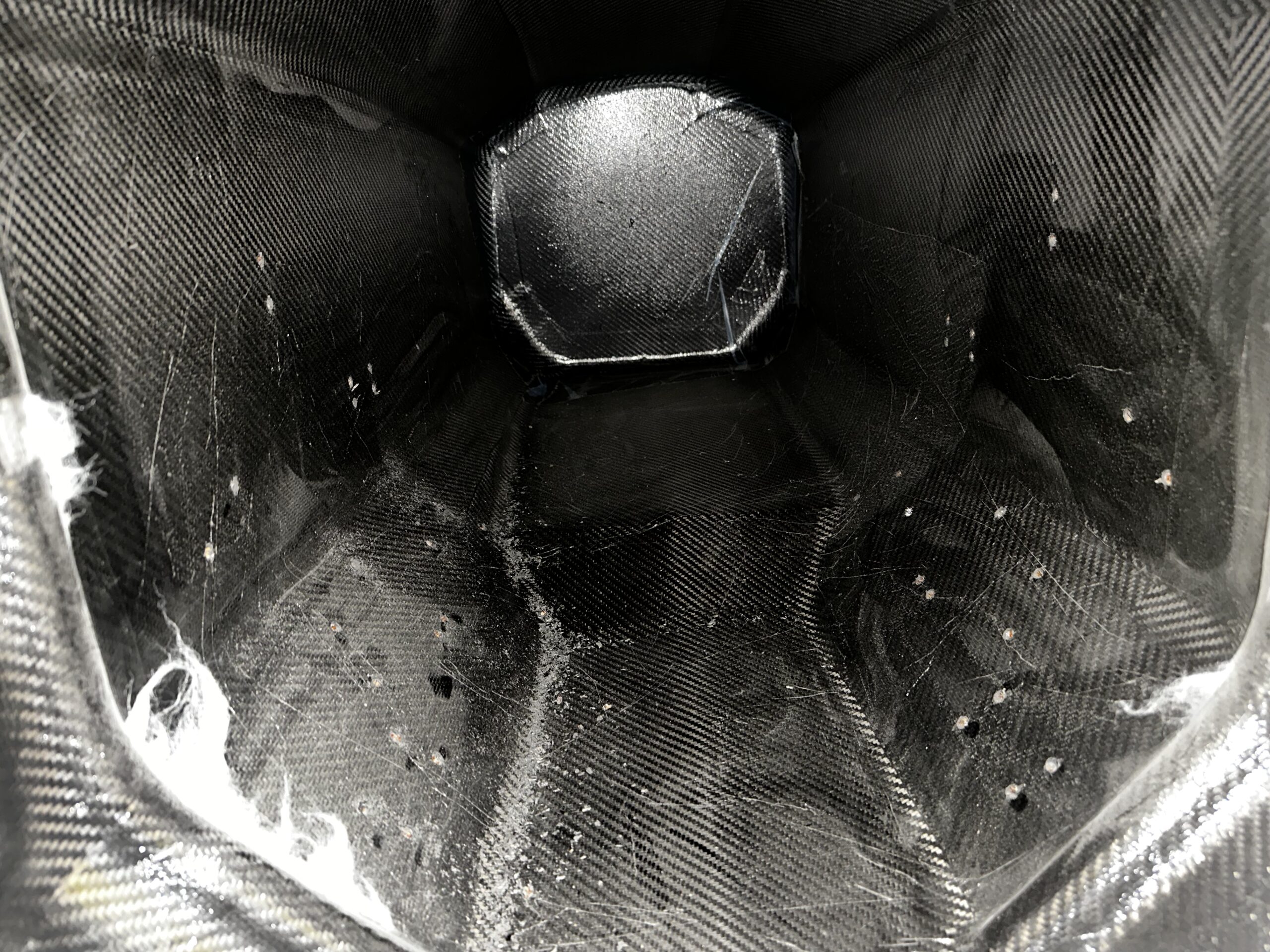
Various other photos, including an interior look at drilled fore holes

Scroll to Top