Cyclone Racing FSAE Adjustable Anti-Dive Clevis

screenshot

A secondary project of mine (see my first one here, my drill alignment jig) was creating a way to adjust the anti-dive characteristics of Iowa State’s Formula SAE 2025-26 car, CR-30. This was determined to be achieved through use of an adjustable front upper fore A-arm clevis, that included several adjustment settings depending on vehicle dynamics preferences.

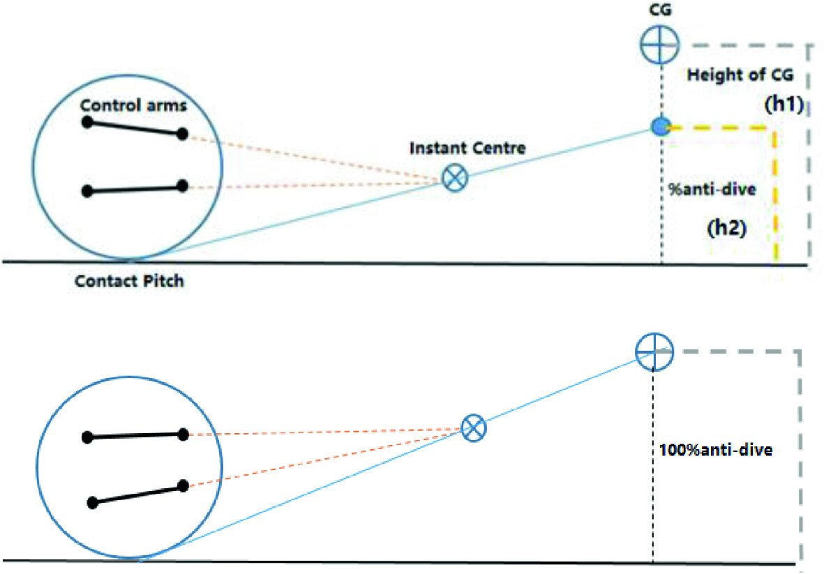
For a quick up-to-speed, anti-dive relates to how much a car resists “diving,” or leaning forward, when heavy braking is applied. In a Formula SAE context, anti-dive affects things like vehicle dynamics and vehicle control preferences, and durability in keeping the front wing from scraping the driving surface.

c17b0f61116eb20e3febf7bbe17ddfaf9731e6d0

Basic visual of anti-dive geometry (Live to Dai). From this view, the clevis changing is the most left, upright one
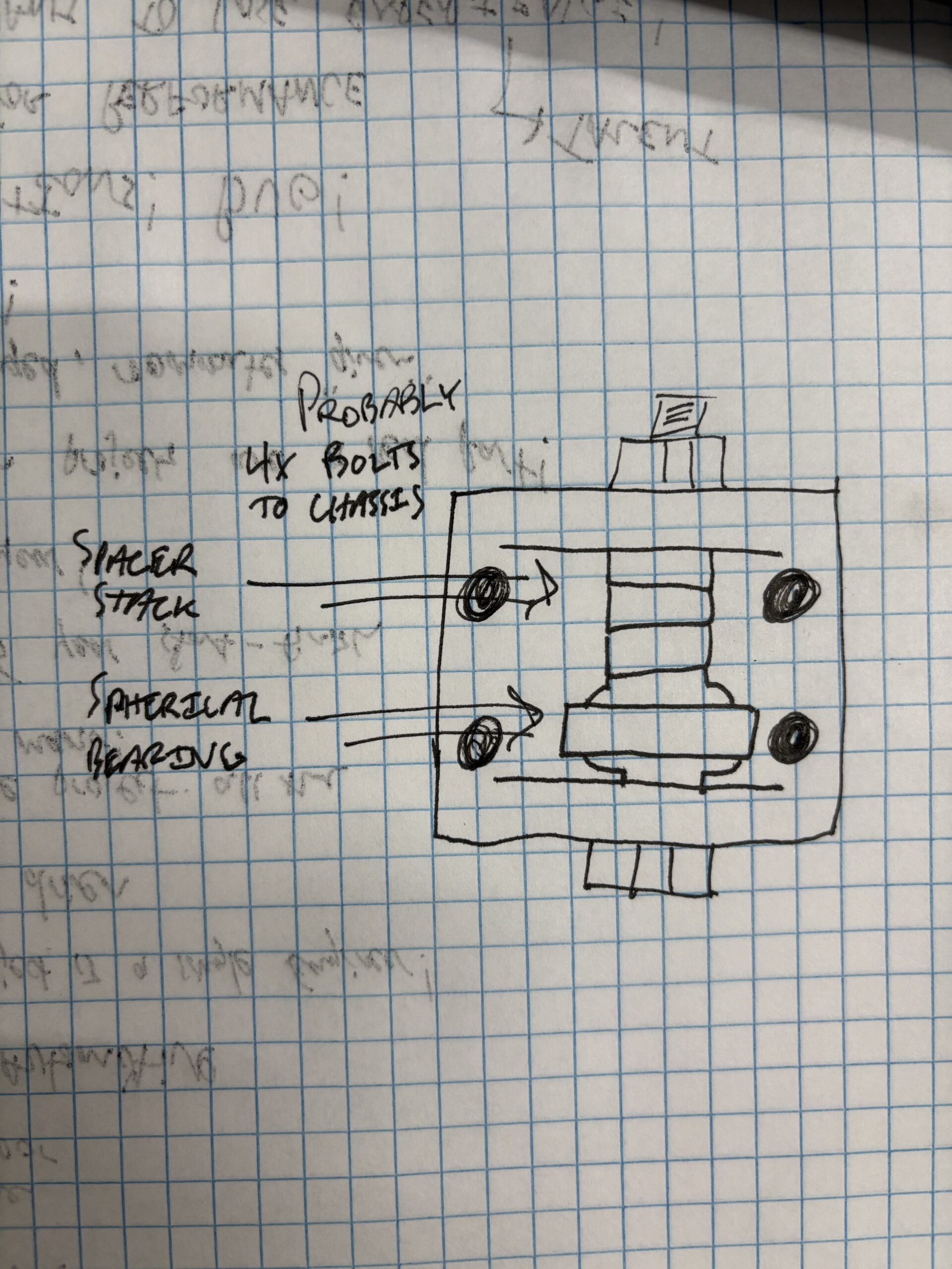
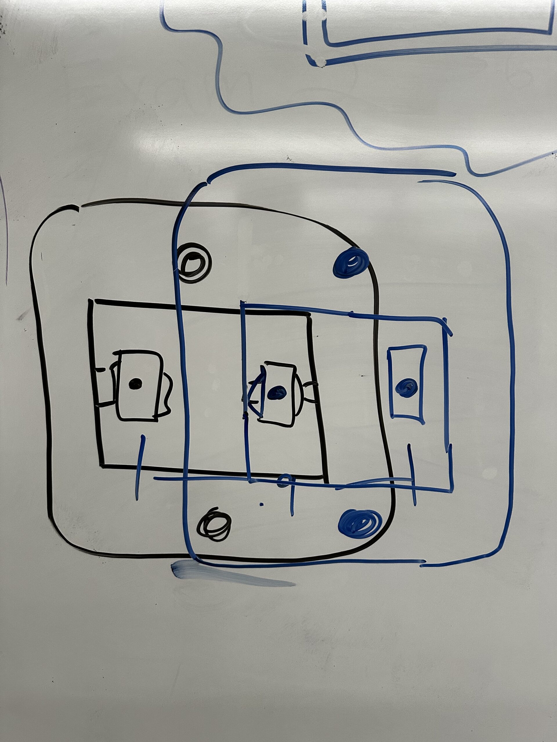
The idea was initially brought to me by our team lead, who had an initial idea sketch drawn up. Essentially, the clevis would function as a wider version of the clevises around the rest of the vehicle, with a longer shoulder bolt and additional spacers that would allow for ideal adjustment values.

Initial sketch given to me by suspension lead (left), as well as secondary clevis system brainstorm (right)

I took a pre-existing clevis designed for 7075-T6 aluminum, made it wider in SolidWorks, and started evaluating load cases in Ansys. Working with our Spring and Damper Engineer, it was initially decided there should be .2 in. to achieve 5% adjustment increments according to VI Grade software. However, after working with our Structural Analysis Engineer for updated load cases and modeling the clevis with the shoulder bolt, modeling additional stiffness from external sleeves was too tricky, and thus allowed the bolt to add far too much compliance to the system when they were removed.

getimage

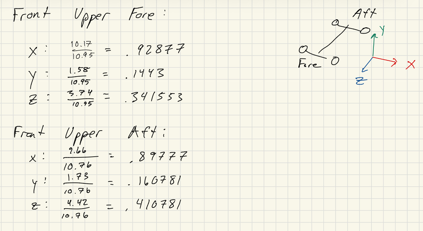
X-Y-Z geometry distribution pulled from SolidWorks model
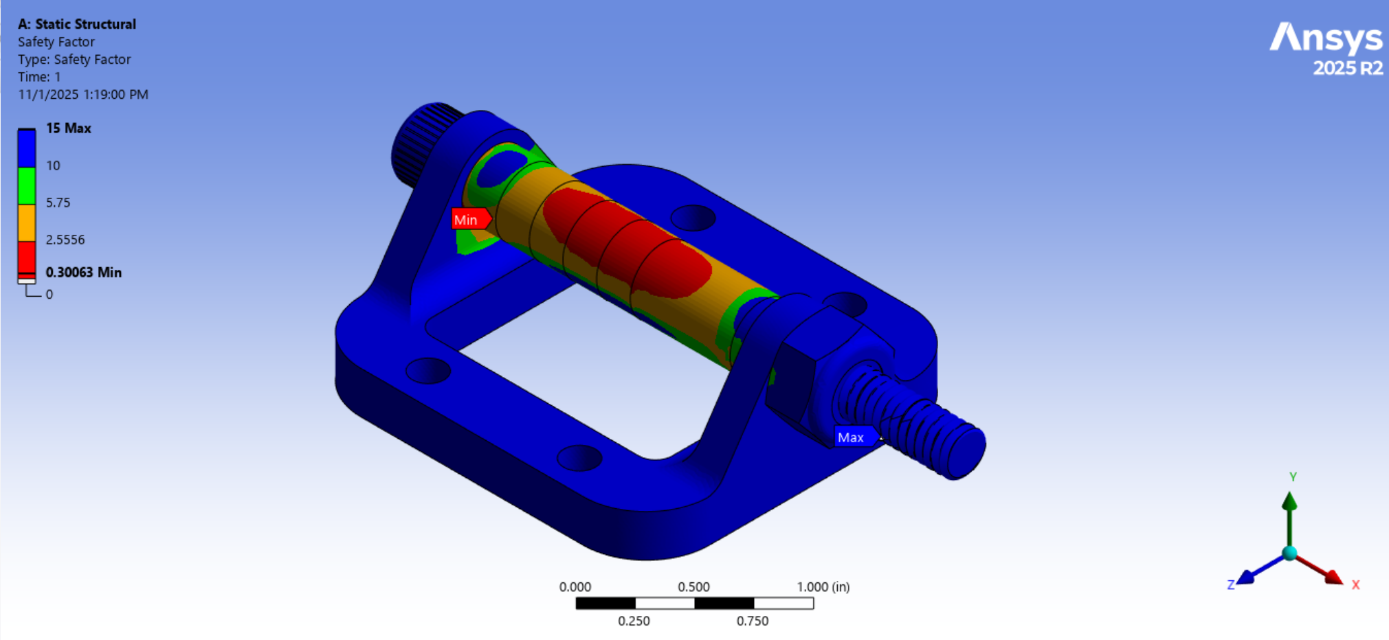
screenshot 2025 11 01 131919

Initial Ansys simulation of assembly factor of safety with bolt; 0.30063 FOS achieved (certain failure and excessive deflection)
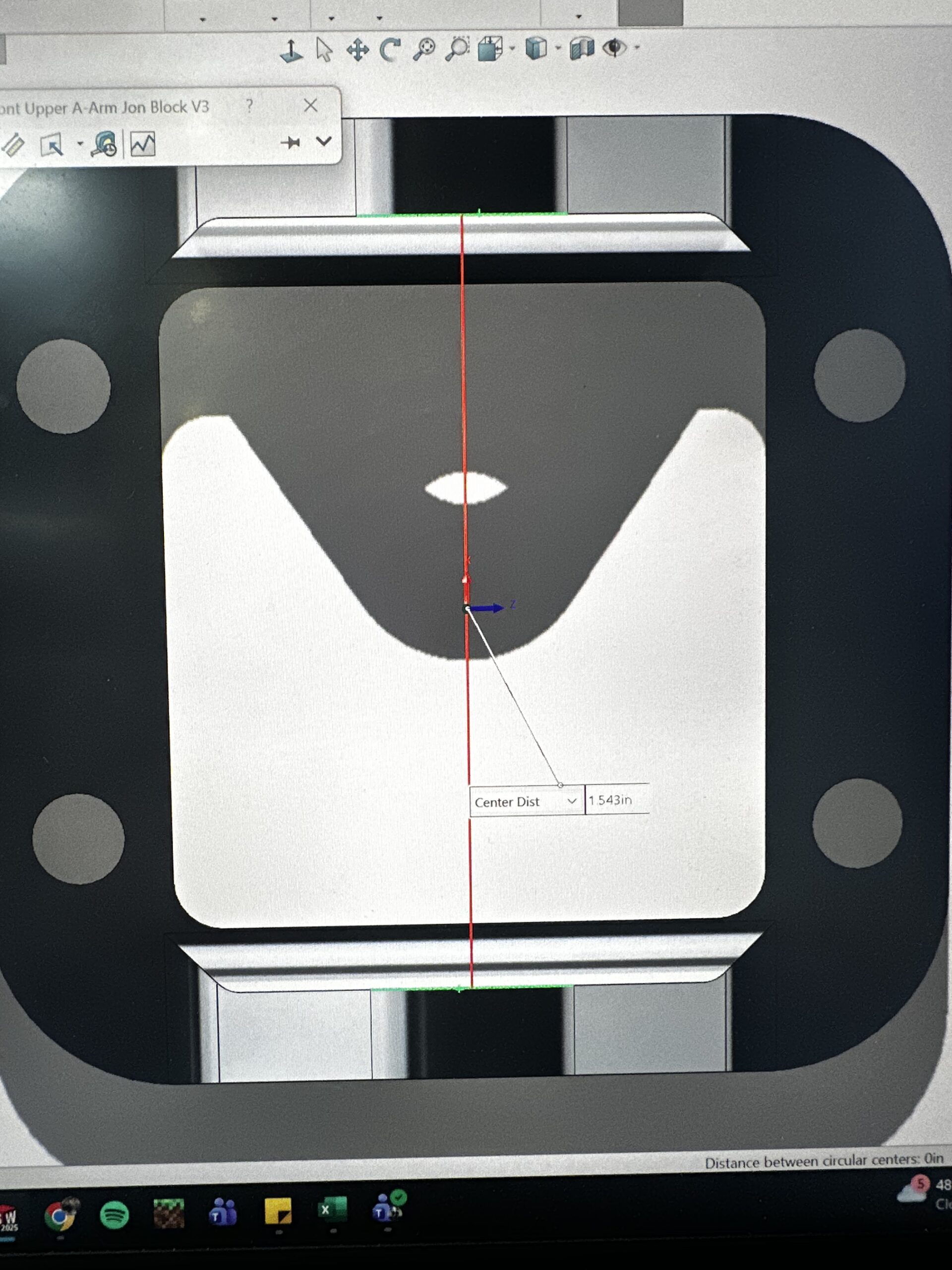
This was remedied by designing a swappable-clevis system as well, where the clevis could be moved to a different set of pre-drilled holes. Along with this, the total maximum adjustability needed was increased to ¾ in. per adjustment for manufacturing reasons, as well as 5% increases being deemed too low, resulting in a total flange-to-flange length of 1.543 in. After updated Ansys simulations, the new factor of safety achieved was 1.68 in a 3G bump scenario.

20251030 212441185 ios

Validating new geometry with SolidWorks Measure feature
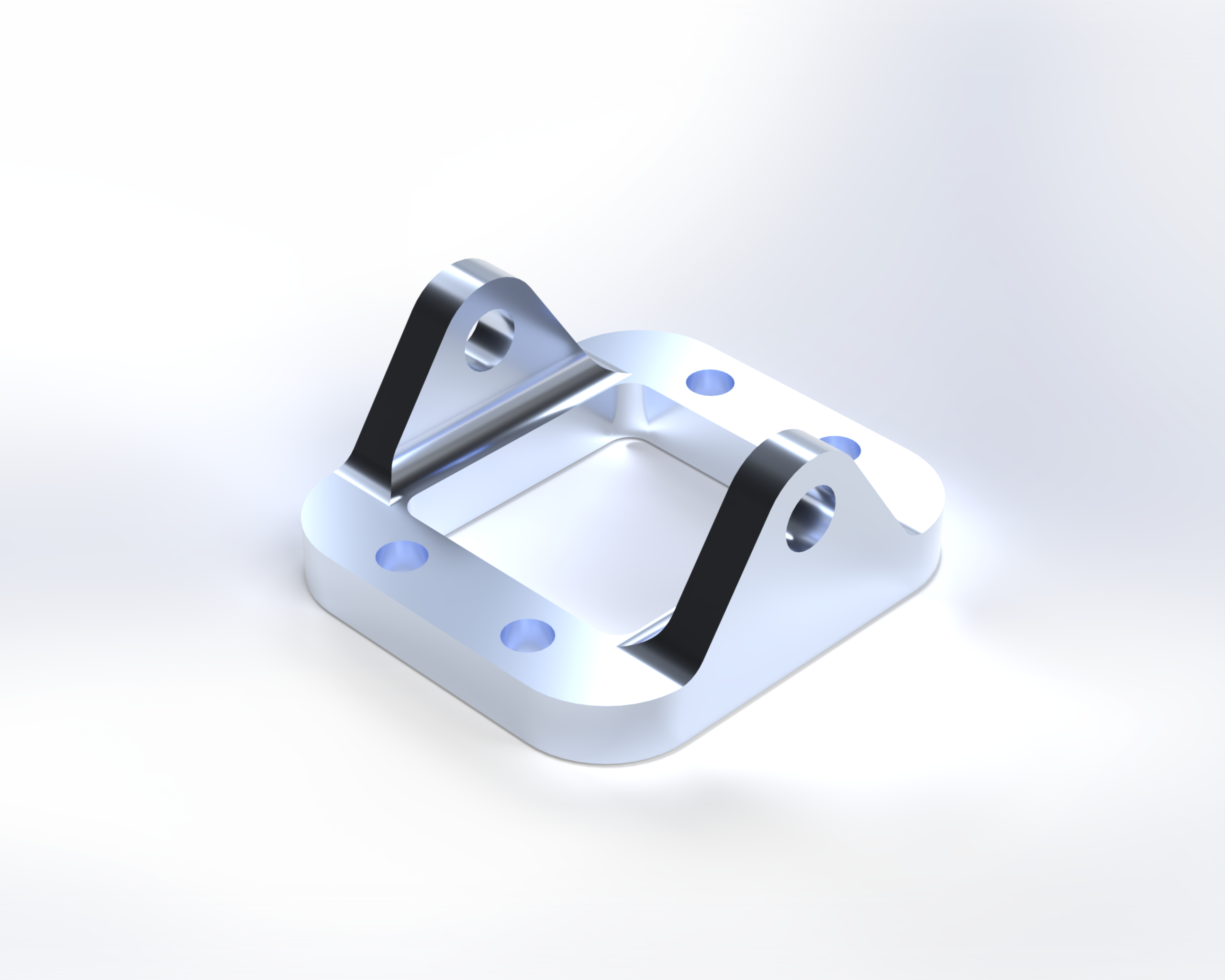
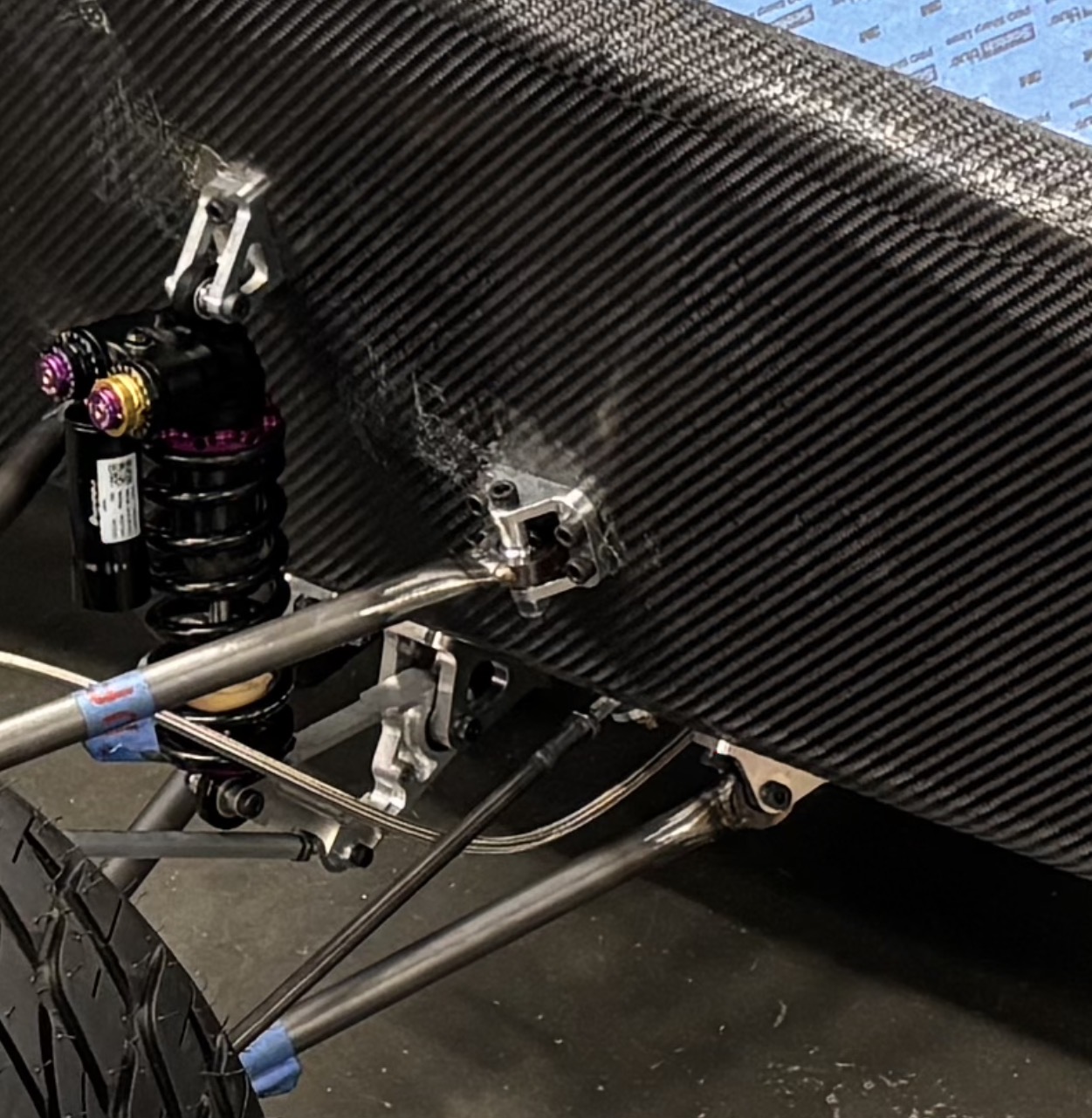
The part was then milled in-house in the Student Innovation Center at Iowa State University and fitted to the car with the custom-lathed spacer that was included. Ultimately, the A-arm point was never moved from the set “default” position during testing, but if needed, the car had 4 new adjustable points for anti-dive.

adjustable a arm jb

Final rendering of finished clevis

img 2604

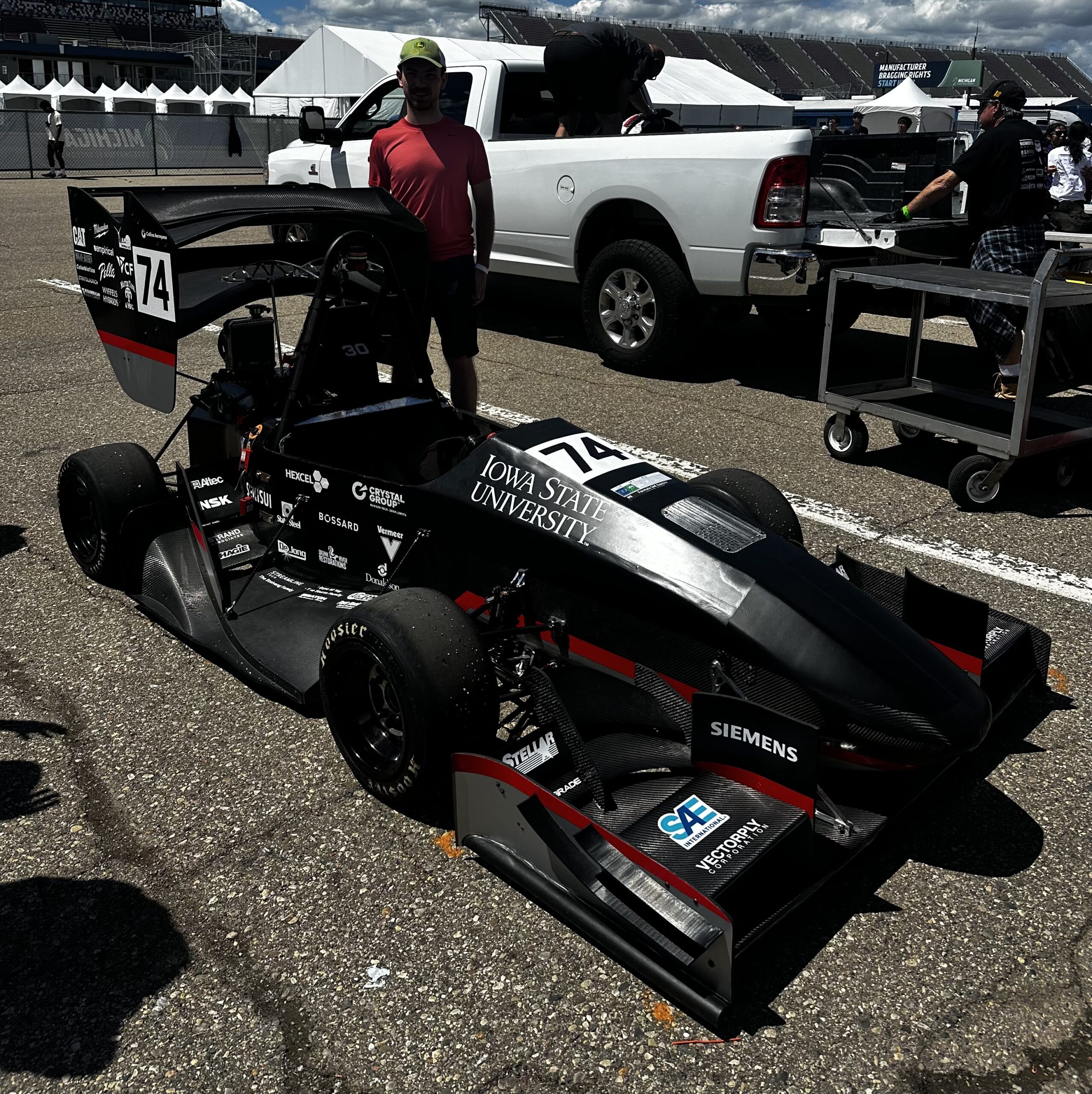
Clevis viewable on finished car at FSAE EV Michigan 2026

Scroll to Top